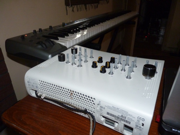
Arduino + 4 x 4051 Multiplexer + 28 POTS = MIDI controller
Pretty straightforward build. 4 multiplexer output pins into the Analog in ports of the Arduino 1,2,3 and 4.
Pitfalls: If you have an Arduino Leonardo: use Serial1.print to write to the TX on the 2nd pin for MIDI. The normal Serial.print writes to the USB TX. (very useful for debugging)
Pitfalls: I have a significant voltage drop therefore I use the first pin on the first multiplexer to read the analog value and use it as a reference when mapping.
ex: midi_value = map(analogValue, 0, myREF, 0, 127);
myRef is read in the setup() function from 4051 chip 0, address 0.
1. Placeholder graphics and placement (Arrangement is identical to MiniMOOG 😉 )

2. Drilled holes and final placement

3. Bottom view with first ribbon cable in place

4. Remaining ribbon cables and +5V / GND connections made

5. Perfboard with BUS and sockets for the multiplexers

6. Wired together + added the MIDI connector

8. Finished product, running NI Massive

10. Close-up of finished product

And the final “product”. 🙂
